
5 Ways To Make Aluminum Parts
Aluminum is one of the most versatile engineering materials available. It is lightweight yet strong, naturally corrosion-resistant, easy to finish, and compatible with a wide range of manufacturing processes. Choosing the right fabrication method for aluminum parts has a direct impact on part quality, lead time and cost.
This guide covers all five major aluminum fabrication methods used in production today. For each process, we explain how it works, what it is best suited for, the tolerances and surface finishes you can realistically expect, and the cost trade-offs involved. By the end, you will have the information needed to select the right process or the right combination of processes, for your specific project.
Quick Answer — The 5 Ways to Fabricate Aluminum Parts
1. CNC Machining. Subtractive process from a solid block or bar of aluminim or extrusion; best tolerances (±0.01 mm+); ideal for complex, low-to-medium volume parts.
2. Extrusion. Heated billet pushed through a die; most efficient for uniform cross-section profiles such as heat sinks, frames and rails.
3. Sheet Metal Fabrication. Laser cutting, punching and bending of flat sheet; fastest route to enclosures, brackets and panels.
4. Casting (Die / Sand). Molten metal poured or injected into a mold; most economical per part at high volume for complex 3D shapes.
5. Forging. Compressive deformation with dies; highest strength and fatigue resistance for structural and high-stress components.
Subtractive Manufacturing
1. CNC MACHINING
Precision and flexibility for complex aluminum components
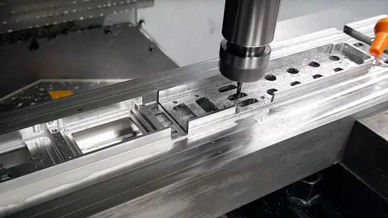
CNC (Computer Numerical Control) machining removes material from a solid aluminum billet, bar or extrusion using high-speed cutting tools guided by a digital program. It is the most accurate and geometrically flexible fabrication method available.
Modern CNC machining centres, including 3-axis, 4-axis and 5-axis configurations, can produce virtually any feature that a cutting tool can reach: pockets, threads, undercuts, slots, compound angles and complex curved surfaces. The process is fully repeatable from first part to thousandth, making it equally suited to a single prototype and a production batch of several thousand pieces.
CNC machining is a subtractive process, meaning material is cut away from a larger block. This results in more material waste than near-net-shape processes like casting or forging, but the trade-off is unmatched precision, surface quality and design freedom. CNC machined parts can be machined from a wide range of aluminum alloys without requiring dedicated tooling for each new geometry.
±0.005 mm
Standard tolerance
±0.001 mm
High-precision
Ra 0.8–3.2 µm
Surface roughness
1–5,000+ pcs
Typical volume
5–15 days
Lead time
ADVANTAGES
✔ Tightest tolerances of any process
✔ Complex geometry — no dedicated tooling per design
✔ Excellent surface finish, ready for anodizing
✔ No minimum order quantity
✔ Wide alloy compatibility (6061, 7075, 6082…)
✔ Fast turnaround for prototypes
LIMITATIONS
X Higher material waste (subtractive process)
X Machine time cost rises with volume
X Not the lowest cost for simple shapes at scale
X Re-fixturing needed for multi-side features
Common Aluminum Alloys for CNC Machining
6061-T6 is by far the most widely machined alloy. It offers excellent machinability, good strength-to-weight ratio and strong corrosion resistance. It anodizes well and is the default choice for most industrial and consumer applications.
7075-T6 is the high-strength option, approximately 40% stronger than 6061, used in aerospace, defence and high-performance applications where weight reduction is critical. It is slightly more challenging to machine and anodize.
6082 is the European structural equivalent of 6061, preferred in EU markets for structural parts. 5052 is preferred for marine and sheet-form applications due to its superior corrosion resistance in salt environments.
Continuous Profile Manufacturing
2. ALUMINUM EXTRUSION
Cost-effective profiles with consistent cross-sections
Aluminum extrusion forces a heated billet of aluminum alloy through a precision steel die, producing a continuous profile with a constant cross-section. The resulting shape can be simple (like a tube or angle) or highly complex (with internal channels, fins and mounting slots).
Extrusion is most efficient for parts that have the same geometry all the way along their length. After extrusion, the profile is cut to the required length, and secondary operations such as CNC drilling, tapping, milling, anodizing and powder coating are applied to achieve the final product.
The process is remarkably material-efficient. Very little scrap is generated compared with machining from billet. Lead times for new die tooling are typically 2–4 weeks, but once the die exists, extrusions can be produced rapidly and economically at scale. The 6000-series alloys (6061, 6063, 6082) are dominant in extrusion due to their excellent extrudability and mechanical properties after ageing.

±0.1–0.5 mm
Cross-section tolerance
±0.01 mm
After CNC secondary ops
6061 / 6063
Most common alloys
High volume
Best efficiency
2–4 weeks
New die lead time
ADVANTAGES
✔ Very low material waste
✔ Low per-unit cost for long profiles
✔ Can include complex internal channels and fin arrays
✔ Good mechanical properties (6000-series)
✔ Die cost much lower than casting tooling
LIMITATIONS
X Cross-section must be constant along the length
X 3D features require secondary CNC operations
X Die tooling investment for new profiles
X Minimum order quantities for new die amortization
Forming & Cutting
3. SHEET METAL FABRICATION
Fast and efficient for flat, bent and formed aluminum parts
Sheet metal fabrication converts flat aluminum sheet into functional parts through a sequence of cutting (laser, waterjet or punch), bending (press brake), and joining (riveting, welding or hardware insertion) operations.
This is the fastest route from a DXF or CAD file to a physical part when the geometry can be unfolded into a flat pattern. Modern laser cutting centres can profile parts from aluminum sheet with excellent edge quality in minutes. CNC press brakes then fold the cut blanks to final shape with repeatable accuracy.
Sheet metal is extremely versatile: thicknesses from 0.5 mm to 12+ mm are routinely processed, and the alloy selection covers 5052 (excellent formability, marine-grade), 6061 (good strength, slightly less formable) and 3003 (maximum formability for non-structural applications). Secondary operations such as tapping, countersinking, PEM nut insertion and powder coating are straightforward to apply.

±0.1–0.3 mm
Bend tolerance
0.5–12 mm
Typical thickness
5052 / 6061
Common alloys
No hard tooling
Laser & bend
3–7 days
min. Lead time
ADVANTAGES
✔ Very fast — no hard tooling required for laser/bend
✔ Cost-effective at medium-to-high volumes
✔ Wide thickness and alloy range
✔ Good for enclosures, covers and structural brackets
LIMITATIONS
X Geometry limited to what can be unfolded flat
X Bend radii constrained by material thickness
X Limited inherent strength in thin-wall sections
X Joining methods (welding, riveting) add operations
Molten Metal Process
4. ALUMINUM CASTING
Economical for complex 3D shapes at medium-to-high volume
Casting pours or injects molten aluminum into a mold cavity, allowing it to solidify into the desired shape. It is the most economical method for producing complex three-dimensional geometries in medium to high volumes, because all features: walls, bosses, ribs, undercuts and text, are formed in a single operation.
Die casting injects molten aluminum under high pressure into a hardened steel mold (die). It produces excellent dimensional accuracy (±0.1–0.2 mm), good surface finish, and high production rates. Tooling cost is significant (typically $5,000–$50,000+ per die), but per-part costs are low at volume. Alloys used: A380, A383, ADC12.
Sand casting uses a sand mold that is broken after each pour, making it suitable for lower volumes and larger parts. Tolerances are looser (±0.5–1 mm), surface finish is rougher, and post-machining is often required for mating surfaces. Tooling cost is much lower. Alloys used: A356, 319, 535.
Investment casting (lost-wax) offers high accuracy and excellent surface finish for smaller, intricate parts, at moderate tooling cost and lower production rates. All three methods benefit from secondary CNC machining of critical surfaces and holes.

±0.1–0.2 mm
Die cast tolerance
±0.5–1.0 mm
Sand cast tolerance
A380 / A356
Common alloys
1,000+ pcs
Best volume range
$5k–$50k+
Die tooling cost
ADVANTAGES
✔ Complex 3D shapes in one operation
✔ Very low per-part cost at high volume
✔ Thin walls and integrated features possible
✔ Die casting gives good dimensional consistency
LIMITATIONS
X High tooling cost for die casting
X Porosity may affect airtight or structural parts
X Lower mechanical properties than forged or machined
X Geometry changes require new or modified tooling
Compressive Deformation
5. ALUMINUM FORGING
Maximum strength and fatigue resistance for structural parts
Forging shapes aluminum by applying compressive force using hammers, presses or rolls with shaped dies. Unlike casting, the metal is never melted: it is deformed in the solid state, which refines the grain structure and eliminates internal voids, producing the strongest aluminum components of any fabrication method.
The grain flow in a forged part follows the contour of the die, creating aligned, fibrous grain lines throughout the cross-section. This is fundamentally different from a machined part (where the grain flow is interrupted by cutting) or a cast part (where grain structure is random). The result is superior tensile strength, fatigue life and impact resistance — all critical for aerospace, motorsport and safety-critical applications.
Forging requires expensive dies (typically $10,000–$100,000+) and is not economical for complex geometries or small volumes. Parts are often CNC machined after forging to achieve final dimensions and surface quality. Alloys 6061, 7075, 2024 and 7068 are most commonly forged.

±0.3–0.8 mm
Forged tolerance
±0.01 mm
Post-machine tolerance
6061 / 7075
Most common alloys
5,000+ pcs
Economic volume
Superior
Fatigue strength
ADVANTAGES
✔ Highest strength and fatigue resistance of any method
✔ No internal porosity or voids
✔ Excellent consistency for mass production
✔ Ideal for heat treatment after forging
LIMITATIONS
X Very high tooling cost
X Geometry limited to what dies can form
X Not suitable for prototypes or low volume
X Post-machining usually required for precision features
Compare the Data
FULL COMPARISON TABLE
The table below summarises the key parameters across all five methods to help you quickly identify the best fit for your aluminum part requirements.
| Method | Best Volume Range | Tolerance | Geometry Freedom | Tooling Cost | Relative Part Cost |
|---|---|---|---|---|---|
| CNC Machining | 1 – 5,000 pcs | ±0.005 mm | Very High | None / Low | Medium–High |
| Extrusion | 500 – High volume | ±0.1–0.5 mm | Constant section only | Low–Medium | Low for profiles |
| Sheet Metal | 10 – High volume | ±0.1–0.3 mm | 2D + bends | None | Low–Medium |
| Die Casting | 1,000 – Mass production | ±0.1–0.2 mm | High (3D complex) | High | Very low at volume |
| Sand Casting | 1 – 1,000 pcs | ±0.5–1.0 mm | High (3D complex) | Low | Low mold, more post-work |
| Forging | 5,000 – Mass production | ±0.3–0.8 mm | Limited by dies | Very High | Low at volume |
Frequently Asked Questions
What are the five main ways to fabricate aluminum parts?
The most common production routes are: CNC machining (milling/turning), extrusion + secondary machining, die casting, sheet metal forming (laser/punch + bend), and additive manufacturing (DMLS/SLM). Each method trades off geometry freedom, surface, tolerance, lead time, and cost.
How do I choose the best method for my aluminum part?
Use a quick filter: low volume/tight tolerances → CNC; long, constant cross-sections → extrusion; high volume/complex shapes → die casting; flat enclosures/brackets → sheet metal; lattice/lightweight or internal channels → metal 3D printing. Consider annual volume, tolerance, surface, and budget.
Which aluminum alloys work best for each process?
CNC: 6061-T6, 6082-T6 (general), 7075-T6 (high strength), 2024 (aerospace). Extrusion: 6063/6060 (excellent extrudability), 6061 (stronger, still extrudable). Die casting: ADC12/A380 (good castability), AlSi10Mg. Sheet metal: 5052-H32 (formable), 6061-T6 (needs larger bend radii). Metal AM: AlSi10Mg is the workhorse.
What tolerances are realistic across the five methods?
CNC: ±0.02–0.05 mm typical, tighter on selected features with CMM. Extrusion profiles: ISO fits on critical faces after secondary CNC. Die casting as-cast: ±0.1–0.3 mm depending on size (machine critical features). Sheet metal: ±0.1–0.2 mm on features, bend angles ±1°. Metal AM: ±0.1–0.2 mm then finish-machine interfaces.
How do finishes (anodizing, powder coat) affect dimensions and appearance?
Anodizing adds ~5–25 µm total (half growth, half penetration); hardcoat is thicker. Powder coat adds more thickness and can soften edges. Mask or post-machine tight bores and mating faces. For cosmetics, specify bead-blast + anodize and define which faces are critical.
What are the biggest cost drivers for aluminum parts?
For CNC: cycle time, setups, tool reach, and small internal radii. For extrusion: custom die cost (one-time) and length/yield. For die casting: tooling cost, parting lines, and porosity control. For sheet metal: number of bends, tight hems, and secondary ops. For AM: build height, support removal, and heat treatment.
Any DFM tips to reduce cost without hurting function?
Increase internal radii to match standard cutters, unify hole sizes, add chamfers/edge breaks, design for single-setup machining or common bend radii, thicken thin walls (≥1.0 mm CNC, ≥1.2–1.5 mm sheet), and call out surface/finish only where needed.
When should I consider extrusion instead of CNC from solid?
If the part is long with a constant cross-section (rails, frames, heatsinks), an inexpensive extrusion die plus light CNC for holes/slots often beats hog-out machining on cost and lead time beyond ~50–200 pcs/year (profile-dependent).
Is die casting suitable for structural or airtight aluminum parts?
Yes for medium/high volumes, but plan for machining of interfaces, porosity control, and heat treatment when strength is critical. Pressure-tight requirements may need impregnation or design changes; consult early for gate/runner and wall-thickness rules (typically ≥1.5–2.5 mm).
Can aluminum sheet parts be both cosmetic and precise?
Yes — use fiber laser/punch for crisp edges, define cosmetic surfaces, and keep consistent bend radii/K-factors. Tight hole-to-bend positions may need hem/notch reliefs or secondary CNC for interfaces.
When does metal 3D printing (DMLS/SLM) make sense for aluminum?
When you need complex internal channels, weight-optimized lattices, or low-volume bespoke components that can't be machined or cast economically. Expect support removal, stress-relief, and final machining on datums.
Do you provide DFM reviews and process recommendations?
Yes — send STEP + drawing, target volumes, and finish requirements. We'll propose the most economical route (among CNC, extrusion, die casting, sheet metal, or AM) and note any design tweaks to hit tolerance, finish, and cost targets.


