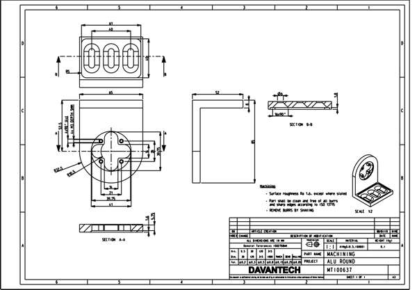
In order to get your parts CNC machined correctly and in an efficient way, it is good to consider these guidelines to design machining parts. A good components design for machining results automatically in cheaper mechanical components. Therefore, you think of internal radii, machining tolerances and the capabilities of a milling machine and lathe.
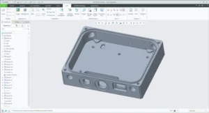
Machined faces:
For each face to be machined, we have to re-position the part onto the machine. This increases the set-up time and at the same time the expenses go up. In addition, Each new position of the workpiece causes more chance to get deviations between machined features on different surfaces. Our advice is to reduce the number of machined faces. However, the use of 4-axis and 5-axis milling machines will reduce the number of re-positioning.
Internal corners radii:
The smaller the internal radii in a part, the smaller the cutting tools. Smaller mills mean more milling passes to remove material. As a result, we get an increase in machining time and production cost. Therefore, it is best to design parts with bigger internal radii. In this way we can mill with larger tools in order to speed up the machining process.
Depth of the cavity:
CNC mills have a limited depth to machine. In addition, the longer the mill compared to its diameter, the more chance it has to start vibrating. As a result, the machined surface is not smooth. Our advice here is to avoid making designs that cannot be machined. Therefore, limit the depth of internal cavities to four times the tool diameter.
Alignment of machined features:
The less the cutting tool has to change position, the faster it will finish milling the cavity. To clarify, the depth and length of the shapes and contours to be machined determine the programming time as well as the machining time. In addition, more complex designs result in more expensive fabrication. Our advice is to keep your designs of machining parts simple. At the same time, it is better to get symmetry in your parts.
Drawings vs 3D files:
Nowadays, design engineers tent to only send 3D files to their supplier, in order to get a quotation or get the parts fabricated. As a result, often features such as treaded holes are missing. Our advice is to add a manufacturing drawing to your CAD model. In this way, it helps the calculators as well as the programmers to save time. Good drawings also help to reduce mistakes. Our recommendation is to have a fabrication drawing which include dimensions, tolerances, notes with surface finish and treaded holes.
Tolerances:
There are the machine tolerances, standard tolerances and specific tolerances which are usually narrow and thus more difficult to control. We produce Machining parts with narrow tolerances slower and there is a chance to have fall-out, resulting in higher costs of manufacturing. Among other guidelines to design machining parts, our advice here is to always verify whether it is really necessary to put narrow tolerances on a certain dimension. Often, designers put tolerances to be certain or because of repetitiveness without considering the higher cost of the part. Modern machinery already fabricate parts with very precise dimensions.
Materials and surface treatment:
Raw materials are sometimes more expensive and the prices are volatile. Therefore, materials that are easier to machine reduce the overall cost of your product. Depending on the use of the part, it is possible it needs surface treatment. In other words, it can be useful to consider a material which does not require such treatment. Our advice is to select the materials carefully and consider how easy it is to process and if it requires any surface treatment. If a part does not need any finish, then don’t ask for it.
The best way to get good parts within the shortest possible time is to cooperate with a machining partner who also has experience in designing machining parts. They know the best what their machines and personnel are capable of.