Connector Manufacturing: Insert Molding with Glow Wire Resistant Plastic
Connectors are essential components used in various electrical and electronic devices to establish a reliable and secure connection between two or more circuits. Connector manufacturing involves several steps to ensure the production of high-quality and durable connectors. One of the critical steps in connector manufacturing is insert molding of metal contacts with a glow wire resistant plastic material.

The different steps involved in connector manufacturing and the advantages of insert molding.
Step 1: Design and Engineering
The first step in connector manufacturing is the design and engineering phase. More specific, we determine the connector’s specifications, including size, shape, and electrical requirements. The connector’s design is crucial to ensure that it can withstand the intended application’s conditions and provide a secure and reliable connection.
Step 2: Tooling and Mold Making
Once we finalize the connector’s design, the next step is to create the tooling and mold required for the manufacturing process. The tooling and mold are custom-made for each connector to ensure consistent quality and accuracy.
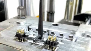
Step 3: Insert Molding
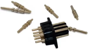
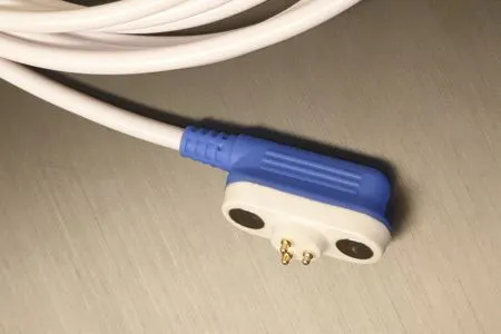
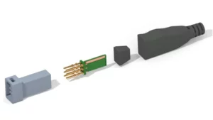
Insert molding is a manufacturing process that involves molding a plastic material around a metal component or insert. In connector manufacturing, insert molding is used to mold a glow wire resistant plastic material around the metal contacts to provide added fire resistance. Therefore, the metal contacts are first placed into the mold, and then the glow wire resistant plastic material is injected into the mold. In this way we get a bonding between plastic and the metal contacts to form a single integrated part.
Step 4: Quality Control and Testing
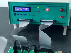
After the insert molding process is complete, the connectors undergo a rigorous quality control and testing phase. Therefore, our quality controllers must ensure the cables meet the required specifications and standards. We perform various tests, including electrical testing, mechanical testing, and environmental testing. We thoroughly verify the connectors’ performance and durability.
Advantages of Insert Molding with Glow Wire Resistant Plastic
Insert molding with a glow wire resistant plastic material provides several advantages over traditional connector manufacturing methods. Some of the advantages are as follows:
- Improved Fire Resistance: Glow wire resistant plastic materials are designed to resist ignition and flaming under conditions similar to those of an electrical fire. By insert molding the metal contacts with a glow wire resistant plastic material, connectors can provide added fire resistance, making them safer to use in various applications.
- Enhanced Durability: Insert molding with a glow wire resistant plastic material also improves the connectors’ durability and strength. The plastic material forms a strong bond with the metal contacts, creating a single integrated part that can withstand environmental stresses and repeated use.
- Cost Savings: Insert molding can help reduce the manufacturing costs of connectors by eliminating the need for additional components and assembly steps. By molding the metal contacts with the plastic material, the manufacturing process is streamlined, resulting in reduced labor and material costs.
Conclusion:
Connector manufacturing is a complex process that involves several steps to ensure the production of high-quality and durable connectors. Moreover, insert molding with a glow wire resistant plastic material is an effective method to improve the connectors’ fire resistance, durability, and strength, while also reducing manufacturing costs. In other words, At Davantech we carefully select the appropriate materials and manufacturing processes to produce reliable and safe connectors for various applications.
Glow Wire Testing of Insert Molded Connectors
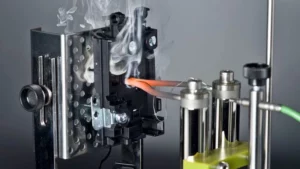
Glow wire resistant material is a specific type of plastic material. More specific, it is designed to resist ignition and flaming under conditions similar to those of an electrical fire. Therefore, we use this material in the manufacturing of electrical components such as connectors, switches, and sockets. Glow wire resistant plastic ensures safety and prevents fire hazard.
We measure the glow wire resistance of a material using a standardized test method. Therefore, we simulate a fire caused by an electrical fault. During the test, a wire is heated to a specific temperature. Next, we apply the glowing wire to the test sample for a set amount of time. The, we evaluate the sample for its resistance to ignition and flaming.
There are several different glow wire tests that are used to evaluate the fire resistance of materials used in electrical products. More specific, each test has its own set of parameters, including the temperature of the glow wire, the duration of the test, and the criteria for determining pass/fail. The following are some of the most commonly used glow wire tests and their temperature specifications:
-
Glow Wire Ignition Test (GWIT):
This test measures the lowest temperature at which a material will ignite when subjected to a glowing wire. To clarify, the laboratory performs the test using a wire heated to 775°C (1427°F) and applied to the sample for 30 seconds. The GWIT temperature is the lowest temperature at which the sample ignites or sustains flaming for more than five seconds.
-
Glow Wire Flammability Index Test (GWFI):
Here we measure the highest temperature at which a material will not ignite or continue to burn when using a glowing wire. More specific, the test is performed using a wire heated to 960°C (1760°F) and applied to the sample for 30 seconds. The GWFI temperature is the temperature at which the sample does not ignite or continue to burn for more than five seconds.
-
Needle Flame Test (IEC 60695-11-5):
This test measures the ability of a material to resist ignition and flame spread when exposed to a small flame. In other words, the laboratory performs the test using a flame with a height of 12mm and a temperature of 650°C (1202°F) applied to the sample for 10 seconds. The criteria for pass/fail are based on the duration of flaming and the extent of damage to the sample.
-
Glow Wire Tracking Test (IEC 60112):
This test measures the ability of a material to resist tracking, which is the formation of a conductive path on the surface of the material. In detail, the analyzer performs the test using a wire heated to 550°C (1022°F) and applied to the sample for a specific duration. The criteria for pass/fail are based on the formation of a conductive path and the duration of the test.
In general, higher temperatures in glow wire tests indicate greater fire resistance of the material being tested. Therefore, we carefully select the appropriate test method and temperature for connector manufacturing, based on the specific application and relevant standards and regulations.