
What Are Overmolded Connectors & Cables
An overmolded connector or cable assembly is a finished electrical product in which a thermoplastic elastomer, typically TPE, TPU, or flexible PVC, is injection-molded directly over the connector body, cable jacket, or cable-to-connector junction to create a single, sealed, integrated component.
Unlike connectors assembled from separate shells, gaskets, and backshells, an overmolded connector has no loose parts or mechanical joints at the cable entry. The overmold material forms a continuous bond with both the connector housing and the cable jacket, sealing the assembly against moisture, dust, and vibration without any additional components.
Overmolded cable assemblies are found everywhere electrical connections are exposed to mechanical stress, environmental contamination, or demanding duty cycles: EV charging handles at public charging stations, M12 sensor connectors on industrial machinery, USB cables on ruggedised handheld devices, cable harnesses inside automotive door modules, and patient monitoring cables in medical equipment.
The core advantage is the elimination of the cable entry as a weak point. Every traditional connector design has a gap between the cable and the backshell, a point where water can enter and where the cable bends most sharply under handling. Overmolding closes that gap permanently. At Davantech, overmolded connector and cable assemblies are one of our highest-volume product families, produced for customers across Europe, North America, and Australia from our factory in Dongguan, China.
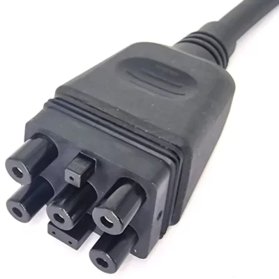
Connector overmolding
Types of Overmolded Connectors
Overmolding is applied across almost every connector category where environmental sealing, cable strain relief, or ergonomic grip are required. The six most common connector types we produce are:

EV & Power Charging Connectors
EV charging connectors, including Type 1 (SAE J1772), Type 2 (IEC 62196), CCS Combo, and custom DC power connectors, are among the most demanding overmolding applications. The handle must be comfortable to grip, sealed to IP55 minimum (IP67 for outdoor public chargers), UV-stable, and resistant to fuels, oils, and cleaning solvents over 10,000+ insertion cycles.
TPU and SEBS-TPE compounds with Shore A hardness of 60A–80A are standard. The overmold incorporates ergonomic grip zones, cable strain reliefs, and often multi-colour sections to differentiate connector rating levels.
Type 1 / Type 2 / CCS | IP55–IP67 | UV-Stabilised | TPU |10,000+ Cycles

Circular Industrial Connectors
M8, M12, and M16 circular connectors are the workhorses of industrial automation, used for sensors, actuators, fieldbus networks (PROFIBUS, PROFINET, IO-Link), and power distribution throughout factories and process plants. Overmolded versions achieve IP67 or IP69K ratings (high-pressure washdown) without requiring a separate backshell or sealing ring.
Both straight and 90° angled overmold versions are produced, and the coding key (A, B, C, D, X) is maintained in the overmold geometry. Standard 3-, 4-, 5-, and 8-pin configurations are available as catalogue items; custom pin counts on request.
M8 / M12 / M16 | IP67 / IP69K | PROFINET / IO-Link | Straight & 90°
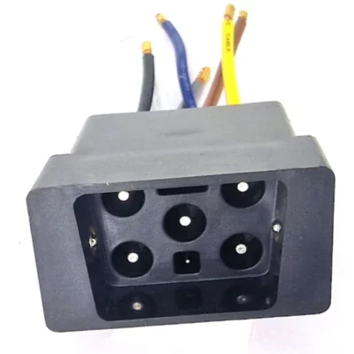
Custom Connector Bodies
When standard off-the-shelf connectors do not meet the form, fit, or function requirements of an application, overmolding enables fully custom connector housings. The contact insert, produced by insert molding over brass or copper alloy terminals, becomes the substrate over which the custom outer body is overmolded.
This approach is widely used for OEM power tools, medical instrumentation, marine electronics, and consumer appliances where a proprietary connector interface is required. MOQ as low as 1,000 pieces for custom tooled connectors is achievable at Davantech.
Fully Custom Geometry |Insert Molded Contacts | OEM / Proprietary | MOQ from 1,000 pcs

High Voltage Battery Connectors
High-voltage (HV) connectors for electric vehicle battery systems, charging infrastructure, and energy storage operate at 400–800 V DC with currents up to several hundred amperes. The overmold layer serves as the primary electrical insulation barrier, touch protection guard, and environmental seal simultaneously.
Materials must meet UL94-V0 flame retardancy, withstand operating temperatures of −40 °C to +125 °C, and maintain dielectric strength across the service life of the vehicle. PA66 or PBT substrates with TPU or TPE-V overmolds are the standard combination for automotive HV connector assemblies.
400 V–800 V DC | UL94-V0 | −40 to +125 °C | USCAR-2 / LV214

Sealed Data & USB Connectors
Waterproof versions of USB-A, USB-C, USB Micro-B, RJ45 Ethernet, and D-Sub connectors are produced by overmolding the connector hood and cable entry in a single operation. These are used in ruggedised handheld scanners, outdoor networking equipment, marine chartplotters, and industrial PDAs where the standard un-sealed connector would fail within months.
IP67-rated USB-C connectors with silicone or TPE overmolded hoods are a fast-growing product line, driven by the adoption of USB-C charging in rugged mobile devices and portable medical equipment.
USB-A / USB-C / Micro-B | IP67 Rated | RJ45 Ethernet | Rugged / Industrial

Medical & Sensor Connectors
Patient monitoring cables (ECG, EEG, SpO₂, blood pressure), ultrasound probe cables, and surgical equipment require connectors that are biocompatible, sterilisable, and highly flexible at body temperature. LSR (liquid silicone rubber) overmolding is preferred for direct patient-contact applications; TPE and TPU are used for reusable non-contact instrument cables.
Sensor connectors for pressure, temperature, flow, and position sensors in process control also require sealed, compact overmolded housings — typically M8 or M12 circular formats with PUR cable jackets that resist hydraulic oils and cutting fluids.
LSR / Biocompatible | ECG / SpO₂ Cables | Autoclave-Safe | Process Sensors
Cable Overmolding
Types of Overmolded Cable Assemblies
Overmolding is applied at five points along a cable assembly, each addressing a different mechanical or sealing requirement.
Strain Relief Overmolds
The most produced type is molded strain relief. Applied at the junction where a cable exits a connector body, panel, or device housing, the point of highest mechanical stress during use. The overmold forms a tapered cone that distributes bending stress over a 20–60 mm length of cable rather than concentrating it at a single bend point.
Design parameter: the taper angle (15–30°) determines the flexibility profile. A 15° taper gives a longer, softer relief suitable for consumer cables. A 30° taper gives a stiffer, shorter relief preferred for industrial and automotive applications where the cable must maintain a fixed exit angle.

Y-Splitters & T-Connectors
A Y-splitter (or T-connector) is an overmolded junction where one input cable divides into two or more output cables. All conductors are crimped, soldered, or terminated at the branch point, and the entire junction is overmolded in a single operation, creating a solid, sealed body with individual strain reliefs on each cable exit.
Common applications include LED lighting networks (one power input, multiple light outputs), automotive sensor wiring (one bus connection, multiple sensor drops), and irrigation control cables. Both symmetrical Y geometries and asymmetric T-configurations are tooled to suit the installation geometry.

Cable Glands & Panel Entries
A cable gland is the sealed interface where a cable enters or exits an enclosure or panel. Overmolded cable glands are co-molded with or attached to the enclosure wall during the assembly process, forming an IP-rated seal around the cable at the penetration point.
The overmolded bore diameter is 0.1–0.2 mm smaller than the cable OD, creating a compression seal. Threaded or flanged versions allow post-installation sealing around an existing cable. Overmolded glands can be produced for one or more cables entering through the same panel location, eliminating the need for individual gland hardware and reducing assembly time significantly.

Connector Boots & Backshells
Cable boots and overmolded backshells protect the mating interface of a connector, the point where the cable plugs into a socket, against environmental ingress, mechanical damage, and accidental disconnection. They are commonly applied to M12, M8, DIN, and circular connectors in outdoor and harsh industrial environments.
Boots differ from strain reliefs in that they cover the full connector mating interface and are designed to be slid over the connector after assembly rather than molded in-mould during the assembly process. Overmolded backshells for military-style rectangular connectors (MIL-DTL-38999, Amphenol PT series) protect the rear of the connector body and cable entry in aerospace and defence applications.

In-Line Overmolded Joins
An in-line join (also called a cable splice or in-line junction) is an overmolded section located midway along a cable — typically at a point where two cable sections are soldered or crimped together, or where a cable changes conductor count or jacket material. The overmold seals the join and restores the cable’s mechanical integrity and IP rating at that point.
Applications include underwater ROV and sonar cables (where field repairs need to be re-sealed), solar panel string cables (where extension cables are joined at the panel frame), and outdoor LED tape light extensions. The in-line overmold can be matched to the cable OD on both sides to maintain a smooth profile along the run.

Industries We Serve
Overmolded connectors and cable assemblies are manufactured for demanding environments across six primary industries. Each places distinct requirements on IP rating, temperature range, material compliance, and connector interface type.
AUTOMOTIVE & EV
The largest market for overmolded cable assemblies. Applications include EV charging handles, BMS wiring harnesses, sensor connectors throughout the powertrain, door and body module harnesses, and high-voltage inter-system cables. Requirements: −40 to +125 °C, IP67/IP69K, resistance to fuels, oils, and brake fluids, USCAR-2 pull-out force compliance.
INDUSTRIAL AUTOMATION
Sensors, actuators, variable-speed drives, and robot arm cables all require sealed, flexible overmolded connections. M12 and M8 connector assemblies with IP67/IP69K ratings are standard. Robot cables require continuous-flex TPU jackets with overmolded strain reliefs rated for millions of bending cycles in cable drag chains.
MEDICAL DEVICES
Patient monitoring cables, surgical instrument cables, ultrasound probes, and diagnostic device leads require biocompatible overmold materials (LSR, medical-grade TPE), chemical resistance to hospital disinfectants, and in some cases autoclave-safe ratings. Cable assemblies must comply with IEC 60601-1 and IEC 62133 where applicable.
MARINE & OUTDOOR
Marine navigation systems, outdoor lighting, solar energy systems, and agricultural machinery require connectors that withstand prolonged UV exposure, saltwater immersion (IP68), and temperature cycling between −25 °C and +85 °C. UV-stabilised TPE and seawater-resistant TPU compounds are used. Many marine cable assemblies also require Lloyd’s Register or ABYC compliance.
CONSUMER & RUGGED DEVICES
Charging cables, headphone cables, gaming peripherals, and earphone cables all use overmolded strain reliefs at the connector end as a standard production feature. Rugged mobile devices, barcode scanners, and body-worn cameras additionally require IP67-rated cable exits and overmolded USB or data connectors to survive daily drops and washing.
RENEWABLE ENERGY
Solar panel string cables, wind turbine yaw and pitch control cables, and battery storage interconnects all require overmolded connections rated for outdoor service over 20–25 year design lives. MC4-type solar connectors use a two-shot overmolded design: an insert-molded contact body followed by a TPE or TPU outer housing rated to IEC 62852 and IP68.
Environmental Protection
IP Ratings of Overmolded Connectors & Cables
The IP (Ingress Protection) rating system defined in IEC 60529 classifies the level of protection a sealed enclosure or connector provides against solid particles and liquids. For overmolded connectors and cables, the IP rating is the primary sealing specification. Here is a practical reference for the five IP ratings most relevant to cable and connector applications:
| IP Rating | Protection Level | Test Condition (IEC 60529) | Typical Applications |
|---|---|---|---|
| IP54 | Dust limited ingress + splash from any direction | Water splashed from any direction for 10 min at 10 litres/min | Indoor Industrial · Light Outdoor · Consumer Appliances |
| IP65 | Dust-tight + protected against water jets | Water jet from any direction at 12.5 litres/min for 3 min | Outdoor Lighting · Garden Equipment · Transportation |
| IP67 | Dust-tight + temporary submersion | Submerged to 1 m depth for 30 minutes | M12 Sensor Connectors · Marine Electronics · Rugged USB Cables |
| IP68 | Dust-tight + continuous submersion | Manufacturer-defined depth and duration (commonly 1–3 m, 4–24 hr) | Underwater Cables · Solar Junction Boxes · EV Battery Seals |
| IP69K | Dust-tight + high pressure / high temp washdown | Water at 80 °C, 80–100 bar pressure, 14–16 litres/min, tested at multiple angles | Food Processing · Dairy / Beverage · Agricultural Machinery |
Note on connector IP ratings: The IP rating of a connector system refers to the mated (plugged-in) condition unless otherwise specified. An unmated connector open to the environment typically has no IP rating. Always verify whether the required IP rating applies mated, unmated, or both — particularly for EV charging connectors, which must maintain IP55 or better when the handle is removed from the vehicle.
Davantech tests all IP-rated overmolded assemblies per IEC 60529. For IP68 assemblies, we offer 100% inline pressure decay testing as an alternative to submersion testing — faster, more reliable, and easily integrated into automated assembly lines.
Material Selection
Materials for Connectors & Cables
Choosing the correct overmold material is critical for IP sealing performance, bond strength, and long-term reliability. The right choice depends on the required IP rating, temperature range, chemical environment, flexibility, and regulatory requirements of the application.
Overmold Materials
| Material | Shore | Temp Range | Best For |
|---|---|---|---|
| TPE (SEBS) | 30A–95A | −40 to 100 °C | Strain reliefs, grommets, consumer cables, general IP sealing |
| TPU | 60A–95A | −40 to 110 °C | Abrasion resistance, robot cables, fuel/oil resistant industrial |
| Flex PVC | 50A–90A | −20 to 70 °C | Cost-sensitive cable assemblies, standard consumer products |
| LSR | 20A–80A | −50 to 200 °C | Medical (biocompatible), high-temp, food contact, sterilisable |
| TPE-V | 40A–80A | −45 to 125 °C | Automotive, chemical resistance, USCAR-2 compliant assemblies |
| PUR | 60A–95A | −40 to 90 °C | Continuous-flex robot cables, cutting-fluid / coolant resistant |
Connector & Cable Substrate Compatibility
| Substrate | Best Overmold | Bond Type |
|---|---|---|
| ABS (connector bodies) | TPE, TPU | Chemical |
| PC / PC-ABS | TPU, TPE | Chemical |
| PA66 / PA6 (Nylon) | TPU, TPE-V | Chemical |
| PBT (high-temp housings) | TPE, TPU | Chemical |
| PVC cable jacket | Flex PVC, TPE | Chemical / Fusion |
| PUR cable jacket | TPU, TPE | Chemical |
| Brass / copper alloy contacts | TPE, TPU, LSR | Mechanical |
| PP / PE | SEBS-TPE (+ interlock) | Mechanical |
Regulatory compliance: Common material certifications required for connectors and cables include RoHS 3 (EU 2015/863), restriction of lead, cadmium, mercury, and other hazardous substances, REACH SVHC, UL94-V0 flame retardancy (required for most connector overmolds), FDA 21 CFR 177 for food-contact or medical-grade materials, and USCAR-2 / LV214 for automotive connector assemblies. Davantech maintains a certified material library covering all of these standards.
Engineering Guidelines
Design Specification
The key dimensional parameters that govern IP sealing performance and mechanical reliability of an overmolded connector or cable assembly. Meeting these from the initial design stage prevents the most common production defects.

1.5–4 mm
MINIMUM WALL THICKNESS
1.5 mm is the absolute minimum for structural integrity. 2.5–4 mm recommended at the cable entry seal for reliable IP67/IP68 performance. Walls below 1.5 mm risk incomplete fill and poor bond adhesion.
1-3°
DRAFT ANGLES
All surfaces parallel to the mold pull direction require 1° minimum draft. Textured surfaces need additional draft of 1° per 0.025 mm texture depth. Insufficient draft causes surface tearing on ejection and tool wear.
−0.1 to −0.2 mm
CABLE BORE INTERFERENCE
The mold bore should be 0.1–0.2 mm smaller than the cable OD to create a compression seal. Too tight damages the cable jacket on insertion; too loose allows leakage past the cable under IP test conditions.
≥ 10 mm
BOND OVERLAP LENGTH
The length over which the overmold material contacts the cable jacket or connector housing. Minimum 10 mm for mechanical retention; 15–20 mm recommended for IP68 assemblies to create a reliable long-path seal against pressure.
15–30°
STRAIN RELIEF TAPER
Taper angle on the strain relief cone. 15° for soft, consumer-style flex relief. 25–30° for stiff industrial or automotive relief where a defined cable exit angle is required. Confirm against the minimum bend radius of the cable.
Injection Gate
GATE & WELD LINE LOCATION
Place the injection gate away from the cable entry seal and any cosmetic visible surface. Weld lines form opposite the gate. A weld line at the cable bore seal point will allow leakage. Verify gate placement before tooling approval.
When specifying an overmolded connector or cable assembly, provide: cable OD and jacket material, connector body dimensions or 3D file, required IP rating, operating temperature range, flex life requirement (bending cycles), and any chemical exposure. Davantech provides a free DFM review covering all specification parameters with every quotation, typically returned within 48 hours.
| Parameter | Typical Range | Notes |
|---|---|---|
| Cable OD | 3 mm – 30 mm | Larger diameters possible; tooling cost increases with cable size. Multi-cable entries (Y, T) accommodated. |
| Conductor count | 1 – 37 | No restriction from overmolding process. Contact count is determined by the connector substrate specification. |
| Overmold hardness | 20 Shore A – 95 Shore A | Softer grades (20–40A) for patient comfort and flexible routing. Harder grades (70–95A) for rigidity and abrasion resistance. |
| Operating temperature | −50 °C to +200 °C | Range depends on material selection. Standard TPE covers −40 to 100 °C. LSR required for 150–200 °C applications. |
| Tooling lead time | 14 – 28 days | Simple single-cavity cable overmold tools: 14 days. Complex multi-cavity connector tools: 20–28 days. |
| Minimum order quantity | No minimum | Davantech can produce samples (10–50 pcs) from production tooling. No separate sample tooling charge for standard geometries. |
Quality & Testing
Testing Standards
A visually acceptable overmolded connector or cable assembly is not necessarily a reliable one. The following tests are performed at Davantech to verify that the sealing, mechanical bond, and electrical performance meet specification before shipment.
Sealing & Environmental Tests
Pressurised water submersion at IP67 or IP68 conditions. Minimum 5 samples per batch; 100% testing available on request via pressure decay method.
Internal pressurisation with air (typically 0.5–1.5 bar) while monitoring for pressure drop. Non-destructive; 100% inline testing option for IP68 cable assemblies.
Seal integrity verified after cycling between −40 °C and +125 °C for 100–500 cycles, confirming no delamination or seal gap formation.
Required for outdoor-rated assemblies. Xenon arc exposure for 500–1,000 hours; inspection for discolouration, cracking, and seal degradation.
Mechanical & Electrical Tests
Tensile load applied axially to the cable while monitoring the force required to dislodge the cable from the overmold. Minimum values defined per product specification.
Cable flexed through a defined arc at a controlled frequency for the specified number of cycles. Electrical continuity is monitored throughout to detect conductor fatigue before visible damage.
90° peel test between the overmold and the connector substrate. Minimum adhesion values are defined per material pair in Davantech process specifications and confirmed during first-article inspection.
100% electrical continuity check on all conductors. Hi-pot (dielectric withstand) testing at 1.5× rated voltage for insulation integrity on high-voltage EV and industrial connector assemblies.
Frequently asked questions about overmolded connectors & cables
What is an overmolded connector or cable assembly?
It is a finished electrical product where a thermoplastic elastomer, typically TPE, TPU, or flexible PVC, is injection-molded directly over the connector body, cable jacket, or cable-to-connector junction to form a single, sealed component. Unlike connectors built from separate shells and gaskets, an overmolded assembly has no loose parts at the cable entry and seals continuously against moisture, dust, and vibration.
What IP rating can an overmolded connector or cable achieve?
Overmolded assemblies commonly reach IP54, IP65, IP67, IP68, and IP69K depending on design and material. IP67 suits M12 sensor connectors and rugged USB cables, IP68 covers continuous submersion for underwater and solar applications, and IP69K handles high-pressure, high-temperature washdown for food and dairy equipment. All IP-rated assemblies are tested per IEC 60529, with 100% inline pressure decay testing available for IP68.
Which materials are used for overmolding cables and connectors?
The main overmold materials are TPE (SEBS) for strain reliefs and general sealing, TPU for abrasion resistance and oil-resistant industrial use, flexible PVC for cost-sensitive assemblies, LSR for biocompatible medical and high-temperature parts, TPE-V for automotive chemical resistance, and PUR for continuous-flex robot cables. Selection depends on the required IP rating, temperature range, chemical exposure, flexibility, and regulatory needs.
What types of overmolded cable assemblies do you produce?
We produce five main types: strain relief overmolds at the cable-to-connector junction, Y-splitters and T-connectors where one cable branches into several, overmolded cable glands for sealed panel entries, connector boots and backshells that protect the mating interface, and in-line overmolded joins that reseal a splice midway along a cable.
What is the minimum order quantity for overmolded assemblies?
There is no minimum order quantity. Samples of 10 to 50 pieces can be produced from production tooling, with no separate sample tooling charge for standard geometries. For fully custom tooled connector bodies, MOQ can be as low as 1,000 pieces.
What is the strain relief taper angle and why does it matter?
The strain relief is a tapered cone that distributes bending stress over a 20 to 60 mm length of cable instead of a single bend point. The taper angle sets the flexibility: a 15 degree taper gives a longer, softer relief for consumer cables, while a 25 to 30 degree taper gives a stiffer, shorter relief for industrial and automotive use where a fixed cable exit angle is needed.
What design information do you need to quote an overmolded assembly?
Provide the cable OD and jacket material, connector body dimensions or a 3D file, the required IP rating, the operating temperature range, the flex life in bending cycles, and any chemical exposure. Davantech returns a free DFM review covering all specification parameters with every quotation, typically within 48 hours.
How are overmolded assemblies tested before shipment?
Testing covers sealing and mechanical performance: IP ingress testing to IEC 60529, pressure decay, thermal cycling between −40 and +125 degrees C, UV ageing for outdoor parts, cable pull-out force to USCAR-2, flex endurance with continuity monitoring, bond peel strength, and 100% electrical continuity plus hi-pot testing on high-voltage assemblies.
Get a Quote for your Cable or Connector Assembly
Send us your drawings, cable spec, and IP requirement. We respond with a free DFM review and competitive tooling + unit price within 48 hours. No minimum order. Worldwide shipping from Dongguan, China.